SC&RA Job Of The Year: Big winners
12 September 2017

Perfecting platforms
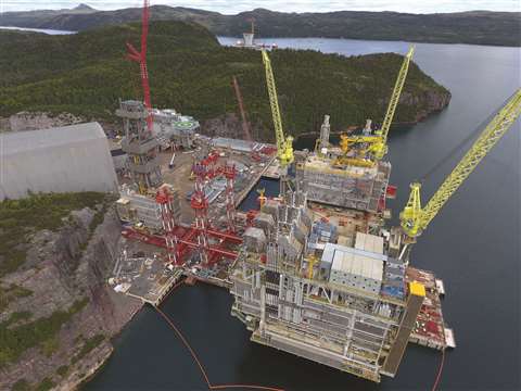
Fagioli completed marine transport and installation operations for one of the most impressive oil and gas projects ever undertaken in the offshore industry.
The installation scope covered the delivery of all modules to the assembly yard in Canada and their assembly into one topside unit on a customised pier. Fagioli also weighed the larger modules, including the Utility Process Module, the Living Quarters and the Drilling Support Module.
The project started in the fourth quarter of 2012 with the Engineering Phase running through to the end of 2013. Site operations ran from early 2014 to October 2016. Edoardo Ascione, Fagioli USA president, said, “Following the delivery of all modules to the assembly yard in Canada, Fagioli was called to prepare and perform one of the biggest load-out operations ever performed in the history of the offshore industry, executed after years of planning and engineering calculation and simulation activity.”
Modules handled by Fagioli included the Utility Process Module weighing 48,501.6 US tons, the Drilling Support Module weighing 4,299 tons, and the Drilling Equipment Set weighing 4,078.5 tons. Ancillaries included the 374 .7 ton Flare Boom, the Life Boat Stations weighing 231 and 253 tons, and the 126.7 ton Helideck.
To the Canadian job site the Fagioli team mobilised 240 axle lines of self propelled modular transporter (SPMT), strand jacks up to 606 tons, a tower lift system for the lifting activity, crawler cranes with a capacity of up to 1,488 tons, and a 7,736 ton capacity elevator system. In addition, there were 64 skid shoes with capacity up to 1,102 tons each for the skidding load-out and load-in activity, and climbing jacks.
The 4,299 ton Drilling Support Module arrived on a barge and Fagioli used more than 200 lines of SPMT for the load-in. The 4078.5 ton Drilling Equipment Set arrived via a transport vessel. Fagioli used more than 200 lines of SPMT for the load-in of this 229.6 foot tall unit.
Strand jacks and towers were used to raise the Drilling Support Module to 19 feet so that it could be positioned onto the elevator system, which raised the module to a height of 118 feet, ready for skidding onto the UPM. The Drilling Support Module was skidded onto the Utility Process Module in one direction and then transversally skidded and jacked down using climbing jacks to its final position within extremely tight tolerances.
The Drilling Equipment Set comprised a 229.5 foot tall, 12,139 pound drill rig tower. It was transported to the job site by sea and then loaded in by SPMT before being lifted onto transport stools for final positioning onto the skidding system. The DES was lifted up to the planned height for the skidding operation into the UPM using strand jacks and the tower lift system.
Final installations were the 354 foot Flare Boom, moved on 32 axle lines of SPMT, and the East Boat Lift Station. Fagioli’s scope of work ended in October 2016. At its busiest time, Fagioli reported that it had up to 225 workers on site.
“This project was one of the most challenging and complex operations ever performed by Fagioli,” Ascione concluded. “The project represented one of the largest fleets of equipment used so far for the assembly of an offshore platform.”
Press room

To lift and set the final press crown, only 6 inches (150 mm) of clearance was available from the top of the strand jack guide to the bottom of the roof structure
To install press components at a plant in Illinois, USA, Emmert International created a unique and creative rigging plan. The press will be the largest in the Western hemisphere. It comprises three base sections, one platen and two crowns. All three base sections were assembled into a single heavy lift of 1,627,096 pounds. The platen was the largest single piece and the upper crown was the tallest set of all four lifts.
“It was critical that the regular plant shipments were not impeded by the delivery and unloading of the press components,” said Terry Emmert, Emmert International president. “It was strictly prohibited to interfere with any of the plant operations during all phases of the press installation.”
The standard way to install the press is for each section to be lowered into the foundation pit using a large crane. Emmert proposed to assemble the base in front of the foundation pit before lifting it as a 1,627,096-pound component. Emmert designed custom rods and lift links to attach and lift it.
With the base section set, four 43 foot columns were placed in each corner prior to stacking the other three components. The crown had to clear the vertical installed columns during the lift and set. This required the tower and strand jack system to lift the crown to the roof line of the building. The rigging configuration had to allow for maximum lift with minimal overhead obstruction. Emmert also designed low profile umbrella strand holders. The fully lifted crown cleared the top of the columns by 4 inches. The top of the lifting system cleared the roof by 6 inches.
On arrival at site, each piece was offloaded with a 450 ton hydraulic lifting gantry onto a 12-line Goldhofer PSTe trailer and moved 100 yards into the press assembly building. A 700 ton gantry system was used to remove and then lower them onto a turntable to be spun for assembly. Each piece was lifted again via gantry and placed for the base section mating and dress out. The fully dressed base section was set in one piece. It weighed in at 1,627,096 pounds, had an overall height of 12 feet, 7 inches and a width of 22 feet, 8 inches and a length of 33 feet, 4 inches.
The 700 ton gantry was used on the 645,000 pound platen to lower it onto trunnion stands and rotate it into the installation position. Repositioning the gantry allowed for loading, travel and installation of the platen above the previously placed base sections.
The crowns were offloaded, using the 450 ton gantry, onto the PSTe and moved into the press assembly building. For the last two crowns Emmert used 20 foot structural tower sections as a base. On top was an elevated 450 ton gantry system with track, beams and strand jacks. The lower crown was lifted first, moved 37 feet, 3 inches and lowered over the previously installed press columns. The Upper crown was then moved into place.
Innovation was key to the success of this project. Equipment used included Goldhofer PSTe and THP transport systems, 450 and 700 ton capacity J&R Lift-N-Lock gantry systems, HSL 2000 strand jack system, tower system, 8 and 12-axle depressed deck rail cars and a BBCX1000 20 axle railcar with a specialized engineered Schnabel attachment.
Span removal

Equipment used included the HSL 2000 heavy lifting strand jack system as well as custom designed strand jack bases, T-brackets and staging platforms
As part of the Sellwood Bridge Removal Project in Oregon, USA, Emmert International was contracted to remove four spans of an old trestle bridge. The weight of the spans ranged from 372,000 to 476,000 pounds and sizes ranged from 190 to 246 feet long by 23 feet to 33 feet wide. Work hours were limited and tidal constraints and geographical challenges had to be overcome. Lead paint on the old bridge meant containment protocols had to be followed when cutting or grinding. Emmert limited these issues by developing attachments that did not require welding. To control camber and flex, the spans were removed in a set order with a cutting plan that mitigated shock loadings and strong shifts. Tension struts were chosen over a compression method to reduce the amount of grinding and welding by building movable attachment brackets.
Before installing the custom modular lift system, pre-installed bracing and pre-tension members were fitted. The beams were then pre-assembled with all lifting components. The strand jack support beam system was installed on lift points at four locations and secured to the existing bridge girders by the engineered Dewidag hold down plate system. The strand jack anchors were connected to T-brackets pre-installed on the bridge spans.Having cut the bridge span free from the bents it was checked for obstructions and lowered to a barge.
Exchanger emergency

Last spring USA-based specialist lifting, moving and industrial installation contractor Barnhart was contacted about an emergency project that involved the removal and replacement of a ground-level exchanger shell at a refinery. There was a five-day turnaround from identification of the problem to installation of the equipment. The refinery team was familiar with Barnhart’s Movable Counterweight Cantilever System (MOCCS). The owner’s idea was to use a 90 ton rough terrain crane with the MOCCS to extract the shell. Physical access limitations precluded use of traditional cantilever beam or traditional jack-and-slide solutions.
The exchanger shell was 17 feet long, 3.17 feet wide and weighed 7,000 pounds. The access route was less than 30 feet wide, and at 15 feet above grade elevation there was a 10 foot wide overhang protruding from the structure’s face. Barnhart developed a custom MOCCS arrangement and secured it to a 750 ton hydraulic turntable secured on six lines of Goldhofer PSTe trailer. Barnhart named the solution the M3A1. It could manoeuvre in all XYZ axes and rotate 360 degrees. The MOCCS system was configured to promote trailer stability and counterweight securement with the ability to stab inside the exchanger, lift out in a very tight area, and rotate the shell 90 degrees for transport out.
Using a 90 ton capacity rough terrain crane, the M3A1 was assembled, in a laydown yard, in about five hours. It travelled into the unit, stabbed the exchanger shell, removed it from its unit, and placed it on a trailer. This process was meticulous – a delicate sequence of raising, lowering, backing and rotating – avoiding live pipes and structural steel.
The replacement process was followed in reverse. Barnhart’s work was completed in 12 hours, including mobilisation, execution and demobilisation. The removal and replacement took two hours.
Offshore module

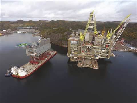
Fagioli transported and installed a 4,500 ton living quarter module onto an offshore platform in Canada that measured 190 x 65 x 100 feet.
The entire process was broken up into the following phases: transportation of the living quarter module from construction hall to completion area; completion of the construction of the living quarters by assembling the Helideck, safety boat stations, and other equipment; jacking up the already assembled living quarters and inserting SPMT with towers and grillage; loading out the living quarter module to the barge; transporting the barge around the Finger Pier; and, finally, hanging the living quarter to the topside.
Operations were executed on a 24-7 basis with a double shift team from June to October 2016. This included 1,600 engineering hours and 2,800 operational man hours. Much of the work was made more difficult because it had to be done in the open sea.
Fagioli deployed 230 axle lines and 10 power packs, plus transport beams, support towers, grillage beams, roll-on roll-off ramps, and a mooring system. For the marine transport Fagioli used a 460 x 140 x 28 foot deck barge with integrated ballast system and two 55 ton bollard pull tugs.
After completion, the LQ was jacked up using Fagioli strand jack towers and the SPMT inserted with 60 foot tall grillage beams and towers. The centre of gravity of the load at that point was more than 100 feet above ground level.
A multipoint 100 percent redundant mooring system consisting of eight 30 ton winches fitted with load cells was used during the load-out on the barge, which was planned to be independent from the tidal cycle.
A large part of the engineering work was the assessment of the barge stability and of weather-induced motions during the marine transportation around the topside (that was sitting on a finger pier).
The barge carrying the LQ module was kept in position by a spacer barge interposed between the finger pier. On removal of one side of the grillage, the LQ was moved against the topside by the SPMT, with the barge ballast system used to keep her keel even.
The SPMT aligned and centred the two large pad-eyes on the LQ with the pins on the topside, while the LQ lower side was aligned on the support base built on the topside. The survey instrumentation was important in controlling and guiding the operation.
The ballast system was finally used to lower the LQ in its final position and disengage the transport equipment.
The Living Quarter Installation onto the topside was on the critical path of the overall project. The very detailed planning and design enabled the execution of SIMOPS (simultaneous operations) by other parties working to complete other parts of the topside. The living quarter module will provide accommodation for up to 220 people offshore.
TBM in record move

For the heaviest item, Fagioli designed and built side beams to interpose between the load and the platform trailer to equally spread the load among the 30 hydraulic axle lines
When Europe’s largest tunnel boring machine had to be moved from Germany to Italy, specialist contractor Fagioli won the job.
Assembled in Germany, the new tunnel boring machine (TBM), named Santa Lucia has a diameter of 52 feet and will be used in the next three years to build the 4.6-mile Variante di Valico tunnel in the Apennines between Bologna and Florence in Italy.
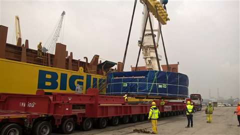
Biggest of the sections was the cutting wheel, with a weight of 904,000 pounds. The components were loaded onto a barge on the river Rhine with the destination set for the Port of Rotterdam. There they were transferred onto a dedicated heavy-lift vessel. On arrival in Italy, at the Port of Ravenna, the sections were directly unloaded onto Fagioli hydraulic trailers, ready for the 105-mile journey to their final destination.
The three largest items were moved by road in a convoy, with transport configurations ranging between 230 feet and 90 feet in length, 32 to 26 feet in width, and between 1,200,000 pounds and 400,000 pounds gross weights. The route consisted of two provincial roads and, for the most part, the main Italian Highway A1 that connects northern and southern Italy.
During the two months of preparation Fagioli surveyed and checked the route and organised the transportation with national and local road authorities. Structural analysis was conducted for 96 bridges and two were load tested. Traffic control plans included: road blocks; the removal of more than 100 signs and lights; and the development of contingency plans. For the heaviest item, Fagioli designed and built side beams to interpose between the load and the platform trailer to equally spread the load among the 30 hydraulic axle lines.
The convoy included Fagioli technical support vehicles and numerous police cars. Assistance vehicle from the Association of National Roads (ANAS) and Autostrade per l’Italia (Highways For Italy) escorted the convoy with more than 100 people present during each of the two consecutive weekend nights of transport on public roads. The maximum speed allowed for the convoy was 12 miles per hour, reduced to 3 miles per hour when moving on bridges and viaducts, with the transit of only one convoy at a time.
The biggest section of the TBM is the 320 ton drive with centre plate, which has a diameter of 29.53 feet. To transport it Fagioli used a 30 axle line modular trailer pushed and pulled by two trucks in a 223 foot convoy. It took two nights to travel between Ravenna and Barberino di Mugello.
Fagioli was in charge of the turnkey operation. This including organising: road transport in Germany (executed by a local supplier); river barge transport on the Rhine; chartering a dedicated H/L vessel to execute the sea transport from the North Sea into the Mediterranean and Adriatic sea; and in-house engineering documentation and detailed plans in accordance with local authorities for the passage of the convoy between trailers and semi-trailers.
This impressive project was executed on schedule and without any accidents.
Long haul

It was a 2,343-mile trek for Barnhart Crane & Rigging to haul a new heat recovery steam generator (HRSG) from Tulsa, Oklahoma to Los Angeles, California. The HRSG had been purchased by the Los Angeles Department of Water and Power for the Hyperion Waste Water Treatment Plant. It was part of a digester upgrade project and measured approximately 43 feet long, 16 feet wide, 16 feet tall, and weighed 225,000 pounds.
Barnhart designed a trailer configuration with two Goldhofer six-line California-style dual-lane trailers, with 7 foot dollies and 9 foot, 1 inch axle spacings at 20 feet wide. It kept axle loadings under 38,000 pounds per line. The permitted dimensions of the trailer configuration were 260 feet long, 21 feet wide, and 17 feet, 11 inches tall with axle loadings of 38,000 pounds per line.
Since the HRSG was already over 16 feet tall Barnhart used its girder system to suspend the load to minimise travel height.
The load had to be permitted with six states: Oklahoma; Kansas; Texas; New Mexico; Arizona; and California. There were also requirements to weigh the load to verify axle weights. Barnhart was also required to obtain 21 local and county permits and get approval from 18 local, county, and district DOT supervisors. Planning and permitting took more than 240 hours and involved 1,100 hours of police and utility support.
Another challenge Barnhart encountered was coordinating driver’s hours, permit curfews, and parking spots for the 260 foot trailer.
From start to finish the project took approximately 11 weeks, including seven weeks for obtaining permits, trailer mobilisation, and loading, and three weeks for the crew to travel the 2,343 miles from Tulsa to Los Angeles. During this time the team worked for more than 2,000 hours without a safety incident or DoT citation.
Final flight

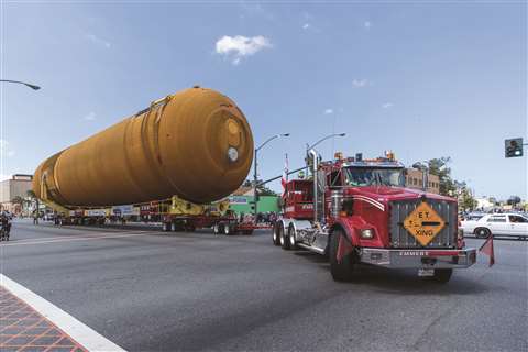
Emmert International hauled the Space Shuttle external fuel tank through the streets of Los Angeles to the California Science Centre
Transporting the only remaining external fuel tank from NASA’s Space Shuttle programme was a job entrusted to Emmert International in the USA.
It was the final journey of a 66,000 pound, 155 foot long, 30 foot wide, and 35 foot tall external fuel tank known as ET-94. A stipulation was that throughout all phases of the project the fragile foam insulation surrounding the tank would not be damaged by any lifting operations, lashings, transport operations, or contact with any obstacles.
Emmert spent 3,400 hours designing the best way to rig, transport and route the historic tank. An hydraulically adjustable four-dolly transporter that interlocks with the existing ET-94 staging and transport system was chosen. The first part of its journey was by barge. ET-94 navigated the Gulf of Mexico, the Panama Canal and cleared customs in San Diego. A second tug was called to manoeuvre ET-94 against strong winds in Louisiana’s canals. The challenge then was to find the best location to transfer the barge back to land before its journey through the streets of Southern California to the California Science Centre in downtown LA.
Marina Del Rey was selected and the remaining journey was just over 16.5 miles. Hauling a huge tank through one of the most highly populated and congested areas in the United States required extensive traffic studies and planning. Emmert’s engineers had to overlay the transporter using two- and three- dimensional modelling with satellite images. The load consisted of the lead (pull) tractor and the four-dolly transporter carrying the cargo. California Highway Patrol (CHP) worked in conjunction with local law enforcement to control traffic and safety
Utility contractors removed street lighting and traffic signals as the tank crawled its way through the crowded urban streets. All utilities were back in operation 15 to 20 minutes after the load had passed.


